Evalm
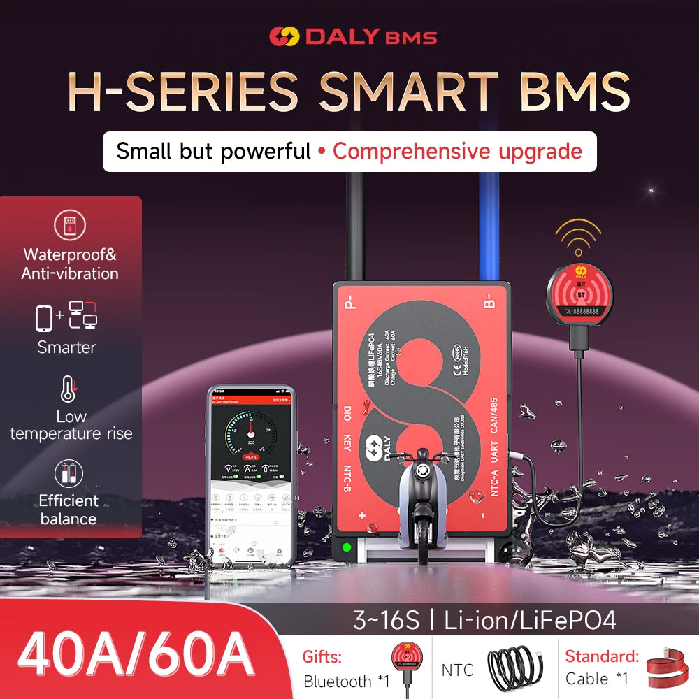
LiFePO4 Battery Protection Board 3S-16S 40A/60A with Balance, Bluetooth, RS485 & CAN for Solar Systems & Street Lights
LiFePO4 Battery Protection Board 3S-16S 40A/60A with Balance, Bluetooth, RS485 & CAN for Solar Systems & Street Lights
Regular price
$36.99 USD
Regular price
$0.00 USD
Sale price
$36.99 USD
Shipping calculated at checkout.
![]() Estimated Delivery: -
Estimated Delivery: -
Quantity
Couldn't load pickup availability

Guaranteed secure & safe checkout.

Product Specifications
- Rated Discharge Current (V): LiFePO4: N(Battery string) * 3.65V
- Charging Voltage (A): 40-60
- Discharge Overcurrent Protection Value (A): 60-90
- Charging Current (A): 40-60
- Charge Overcurrent Protection Value (A): 60-90
- Main Circuit On-Resistance (mΩ): (Passive Equalization Function 100±30mA)
- Equalization Turn-On Voltage (V): LiFePO4: 3.4 (Can be set up)
- Equalize Opening Differential Pressure (mV): 20 (Can be set up)
- Balance Current (mA): Li-ion, LiFePO4: 100±30
Protection Features
Short Circuit Protection
- Conditions: External Load Short Circuit
- Delay (uS): 10-500 (Actual test subject to customer's battery)
- Release: Remove load to release
Single Cell Over-charge Protection
- Protection Voltage (V): LiFePO4: 3.75±0.05 (Can be set up)
- Protection Delay (S): 1±0.8
- Recovery Voltage (V): LiFePO4: 3.65±0.05
Single Cell Over-discharge Protection
- Protection Voltage (V): LiFePO4: 2.2±0.05 (Can be set up)
- Protection Delay (S): 1±0.8
- Recovery Voltage (V): LiFePO4: 2.3±0.05
Charge/Discharge Over-current Protection
- Protection Delay (S): 1±0.8
- Release Condition: Removing the load
Temperature Protection (℃)
- Operating Temperature: Charging: -35~75, Discharge: -35~75 (can be set up)
- Storage Temperature: -40~85
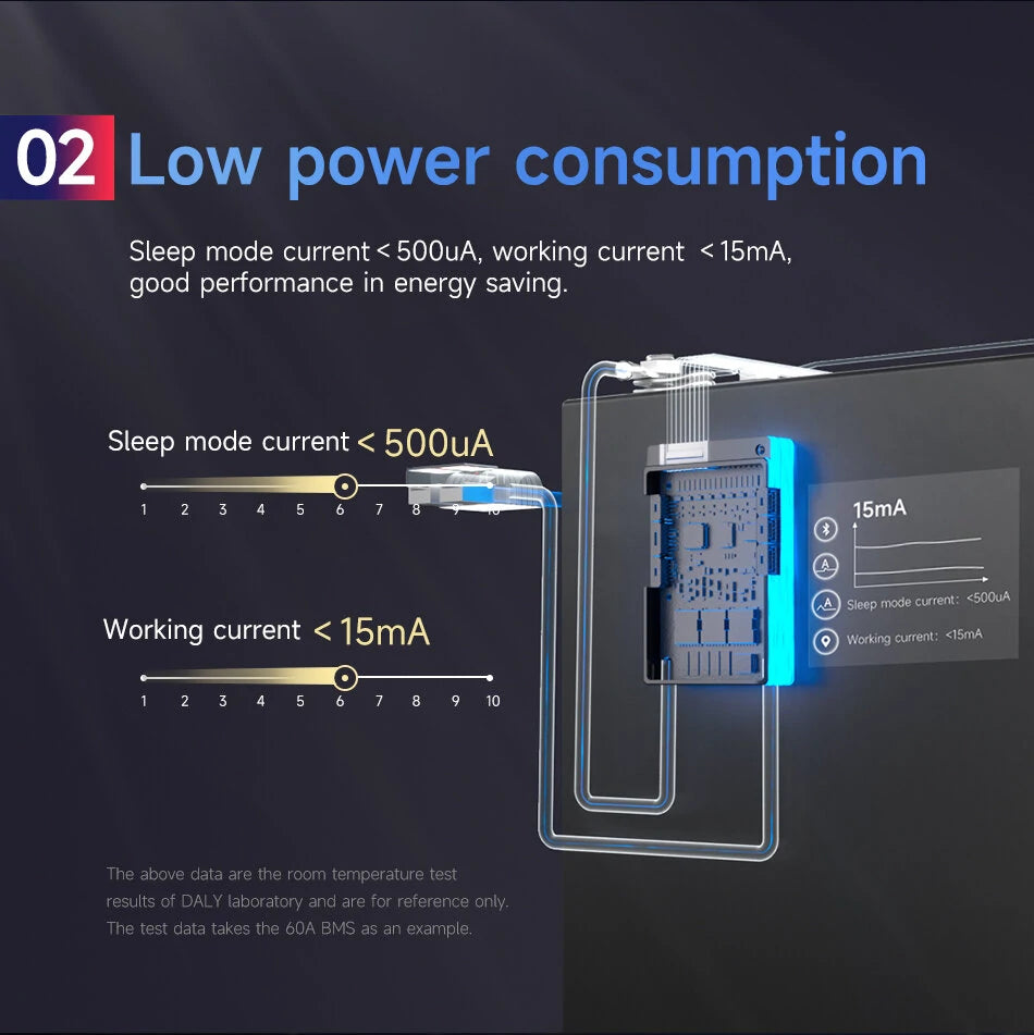
Power Consumption
- Current Consumption: Working Current (mA)
- Resting Current (uA):
- Sleep Time (S): 3600
- The above data is based on temperature test results from the DALY laboratory, for reference only.
- For customized services, please consult customer service for details.
Installation and Wiring
-
Solder the Sampling Cables:
- The first cable (black) connects to the negative terminal of the battery.
- The second cable (red) connects to the positive terminal of the first battery string, and so on.
- Check the Cables: Measure the voltage between two adjacent cables starting from the header to ensure correct connections.
-
Connect the Output Wires:
- Connect the B- wire of the BMS to the total negative terminal of the battery pack.
- Plug the sampling cable into the BMS and check consistency in voltage between B+ & B- and P+ & P-.
Activating the BMS
The BMS activates automatically on first use. If dormant, activate it using one of the following methods:
- Use a key switch.
- Press buttons on the Bluetooth module or SOC indicator.
- Use CAN/RS485 communication or connect via Bluetooth to a mobile app.
- Charge or discharge the battery.
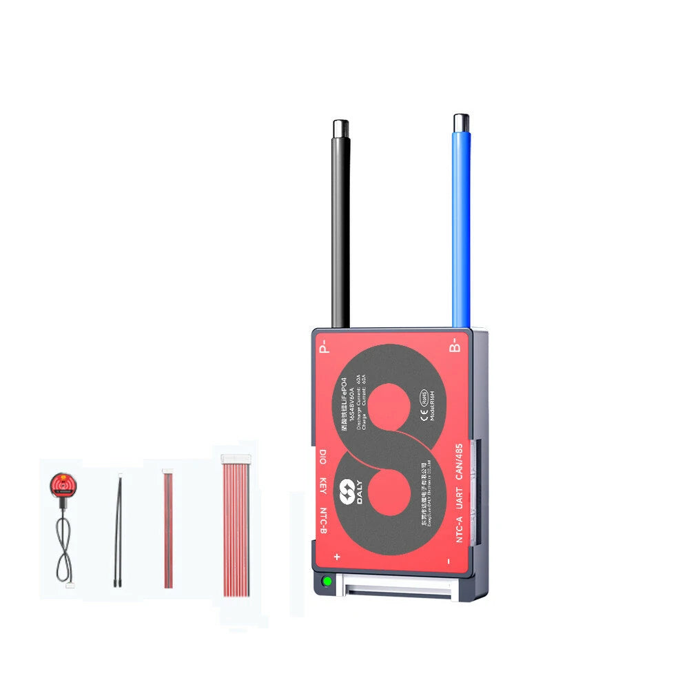
Package Includes
- 1 x Smart BMS
- 1 x Cable
- 1 x Bluetooth Module
- 1 x NTC
- 1 x CAN/485 5-pin