Evalm
STM32 Data Acquisition Module, 16-Channel 12-Bit ADC, USB & UART Interface
STM32 Data Acquisition Module, 16-Channel 12-Bit ADC, USB & UART Interface
![]() Estimated Delivery: -
Estimated Delivery: -
Couldn't load pickup availability


Product Overview
- Product Name: STM32 16-way AD Sampling Module
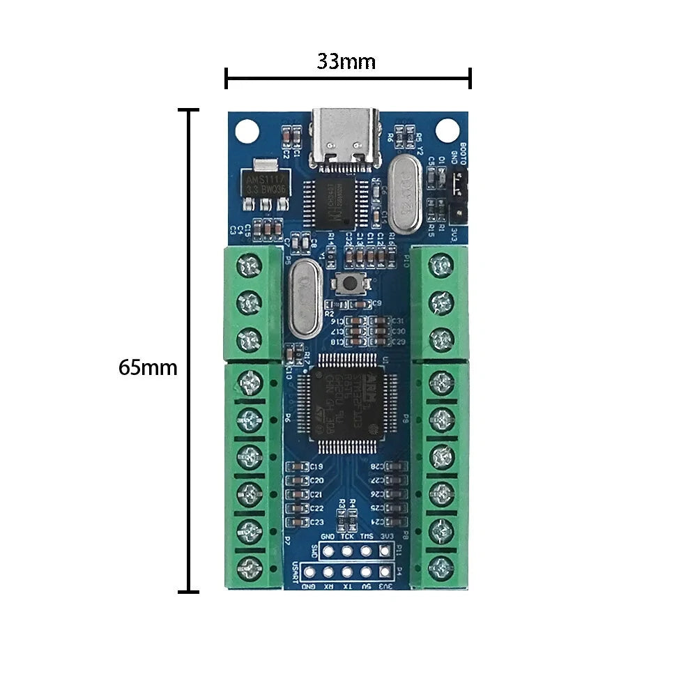
- Product Size: 33 x 65 mm
- Product Interface: Type-C Interface Power Supply
- Product Weight: 25 g
- Product Material: FR-4
Description
The STM32 16 Channel ADC Sampling Module leverages the STM32F103R8T6 microcontroller’s internal 16 channel ADC resources as its sampling core. Data is transferred to memory via STM32’s internal DMA, reducing CPU load and increasing sampling stability and accuracy. Additionally, the onboard USB-to-serial chip (CH340T) enables data transfer to a PC through a Type-C cable, supporting code burning functionality.
Features
- STM32F103R8T6 as the main control chip.
- Includes onboard CH340T chip for easy data viewing on a PC via a Type-C data cable.
- Reserved UART serial communication and SWD serial debugging interfaces.
- Offers up to 16 AD acquisition channels with 12-bit resolution (4096).
Package Includes
- 1x STM32 16 AD Sampling Module
- 1x 9-pin Single Row Pin
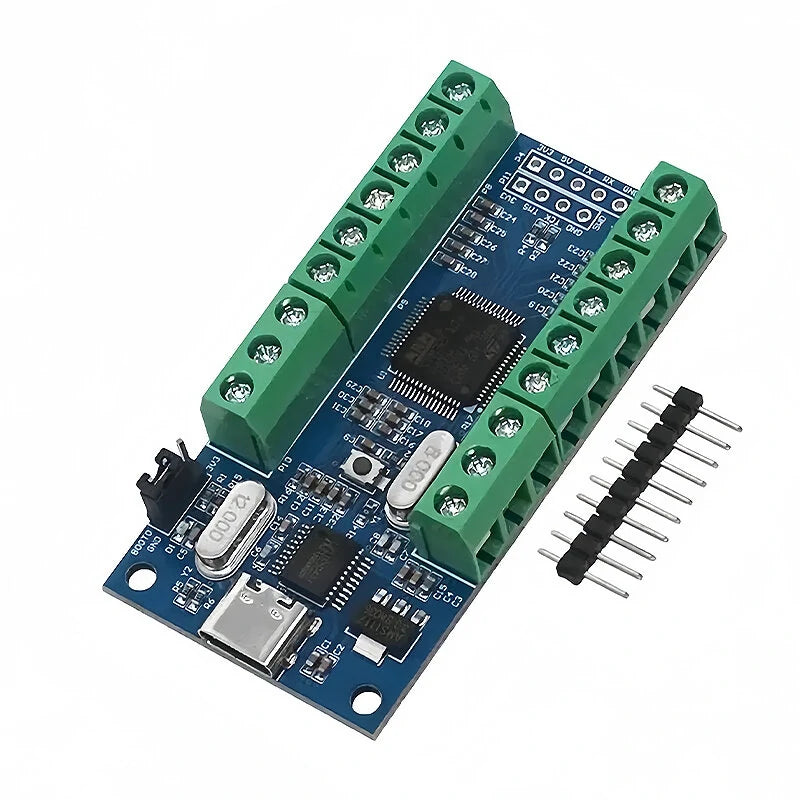
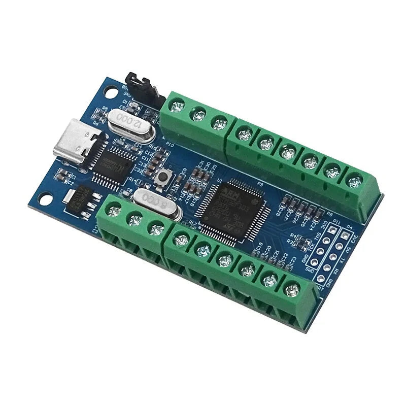
Hardware Introduction
- ADC Acquisition Channel: 8-channel 15
- BOOT0 Port: Connect to 3V3 in burning mode, and to GND in running mode
- CH340T Chip: USB to Serial Port
- Type-C Interface
- Reset Button
- Linear Regulator AMS117: Converts 5V to 3.3V
- Additional ADC Acquisition Channel: 0-channel 7
- UART Serial Communication Interface
- SWD Serial Debugging Interface
- MCU: STM32F103R8T6
Usage Instructions
1. Interface Description:
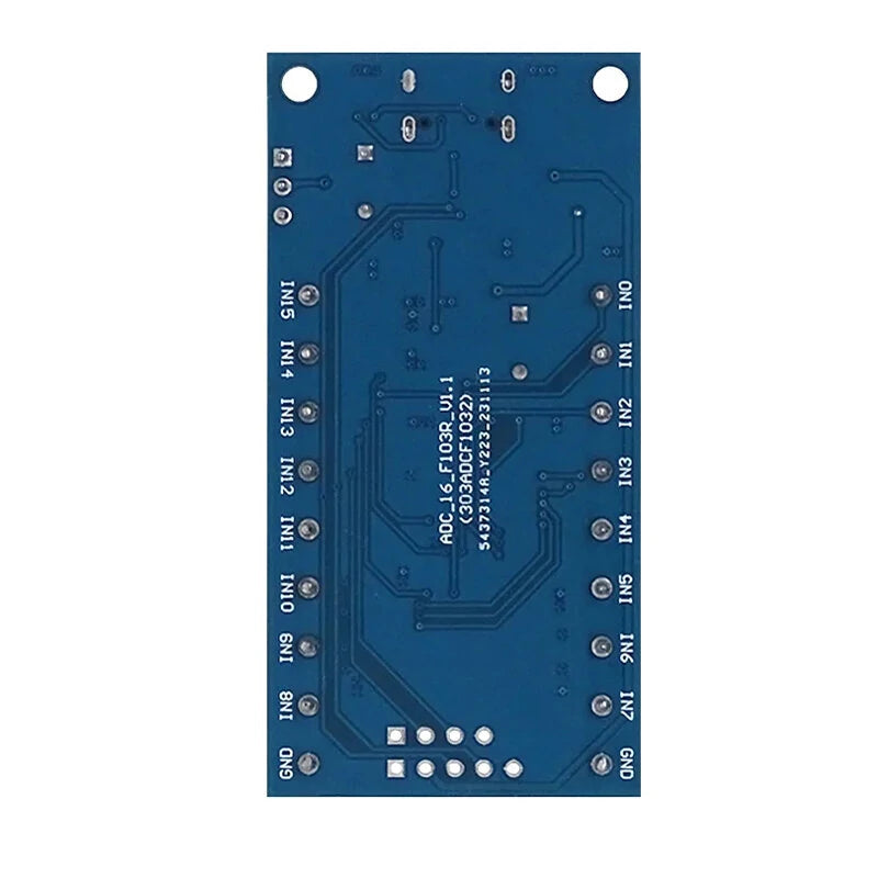
- IN0-IN15: 16 AD sampling voltage inputs
- GND: Common ground interface for power supply/sampling voltage
- TX, RX: UART communication interface
- TCK, TMS: SWD debug interface
- 3V3/5V: Reserved 3.3V/5V power input port
2. PC Usage:
Install the CH340 USB-to-serial port driver, connect the module to a computer, and link IN0-IN15 to the positive sampling voltage, with GND linked to the negative sampling voltage. Open the serial port debugging assistant, select the correct COM port and baud rate (115200), and view AD sampling results updated every 500ms. Modify this interval in the source code as required.
For a sample 3.3V voltage provided by the module, connect a DuPont line between the module’s 3.3V pin and any IN0-IN15 pin. The sampling results via the serial port will reflect the wiring adjustment.
3. MCU Connectivity:
To obtain sampling data directly through an external MCU, connect the MCU’s 3.3V, RX, TX, and GND to the corresponding pins on the module. Alternatively, power the module with a 5V supply. Reference the source code for data transmission protocols.
4. Firmware Update:
For source code modifications and reprogramming, insert the module into a computer’s USB port, connect the jumper cap to the 3V3 end, and post-programming switch back to GND. Launch FlyMcu programming software, select the hex file, and configure port and waveform settings before starting the programming process. Don’t forget to press the reset button afterward.
Important Notes
- The AD sampling inputs IN0-IN9 can be used partially or fully. Channels with no input will output random values. Unused ports can be used as standard I/O ports by adjusting the program.
- Ensure the voltage does not exceed 3.3V to avoid damaging the chip.